


 English
  中文简体
中文简体  русский
  Español
  عربى
عربى  Français
  Português
  Deutsch
  Türk
Türk
JINYE
JINYE
JINYE
JINYE
JINYE
JINYE
JINYE
JINYE
JINYE
JINYE
JINYE
JINYE
JINYE
JINYE
JINYE
JINYE

What is the working principle of a Fixed Pitch Propeller?
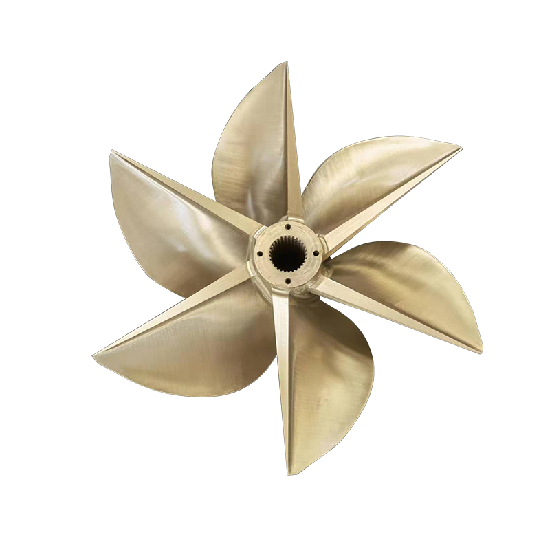
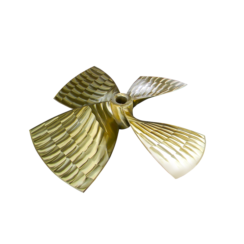
A Fixed Pitch Propeller generates thrust by rotating blades set at a permanently fixed angle relative to the plane of rotation. As the blades spin, their cambered aerofoil cross-section accelerates water rearward, and by Newton's Third Law, the reaction force drives the vessel forward. The blade angle — called the pitch — cannot be changed during operation, so thrust and speed are controlled entirely by varying the engine RPM. This simplicity of mechanical design is both the defining characteristic and the primary operational advantage of the fixed pitch propeller.
In more precise engineering terms: the blade pitch angle determines the theoretical distance the propeller would advance through the water in one complete revolution if there were no slip. A propeller with a pitch of 800 mm would theoretically move the vessel 800 mm forward per revolution in an ideal, frictionless medium. In practice, slip — the difference between theoretical and actual advance — accounts for 10 to 20% of the theoretical pitch distance in well-designed commercial vessels under normal operating conditions. (Source: Carlton, J.S., Marine Propellers and Propulsion, 3rd Edition, Butterworth-Heinemann, 2012.)
The Hydrodynamic Mechanism: How Rotating Blades Create Thrust
The thrust-generating mechanism of a fixed pitch propeller is fundamentally identical to the lift-generating mechanism of an aircraft wing. Each propeller blade has an aerofoil cross-section — a curved pressure face and a flatter suction face — that produces a pressure differential as water flows across it.
Pressure Distribution Across the Blade
As the propeller rotates, water approaching the blade leading edge is divided into two streams. The stream flowing over the suction face (back of the blade, facing forward) travels a longer path and accelerates, reducing pressure according to Bernoulli's principle. The stream flowing over the pressure face (driving face, facing aft) travels a shorter path and decelerates, increasing pressure. This pressure differential across the blade chord generates a hydrodynamic force directed predominantly ahead — the thrust force that propels the vessel.
The total thrust force (T) produced by the propeller is described by the actuator disk theory relationship:
T = rho × A × V × (V2 - V1)
Where rho is water density (approximately 1,025 kg/m3 for seawater), A is the disk area swept by the blades, V is the mean velocity through the disk, V2 is the slipstream velocity downstream, and V1 is the inflow velocity ahead of the propeller. (Source: Carlton, J.S., Marine Propellers and Propulsion, 3rd Edition, 2012; Burrill, L.C., Transactions of the Institute of Marine Engineers, 1944.)
The Role of the Pitch Angle in Thrust Generation
The pitch angle sets the angle of attack at which the blade meets the incoming water. For a fixed pitch propeller operating at its design condition, this angle of attack is optimized to produce maximum hydrodynamic efficiency — typically in the range of 3 to 8 degrees of angle of attack on the blade sections at design RPM and vessel speed. When the vessel operates away from the design condition (either at lower speed or higher RPM than designed), the effective angle of attack changes because the advance velocity of the water relative to the blade changes, even though the blade's geometric pitch remains constant. This is why a fixed pitch propeller has a single efficiency peak at its design operating point.
Slip: The Difference Between Theory and Reality
Propeller slip is the fundamental efficiency parameter that separates theoretical from actual performance. Real slip (s) is defined as:
s = (P - Va/n) / P
Where P is the geometric pitch (meters), Va is the speed of advance (m/s), and n is the rotational speed (revolutions per second). A typical well-matched fixed pitch propeller on a commercial cargo vessel achieves real slip values of 12 to 18% at design draught and full load. Tugs and heavily loaded vessels may experience higher slip values of 25 to 35% due to the large thrust demands relative to vessel speed. (Source: Molland, A.F., Turnock, S.R., Hudson, D.A., Ship Resistance and Propulsion, Cambridge University Press, 2011.)
Key Design Parameters That Govern Fixed Pitch Propeller Performance
The working principle of a fixed pitch propeller cannot be fully understood without appreciating the interrelated design parameters that determine its operating characteristics. These parameters are fixed at manufacture and define the propeller's entire performance envelope.
| Design Parameter | Definition | Effect on Performance |
|---|---|---|
| Diameter (D) | Overall tip-to-tip measurement of the propeller disc | Larger diameter increases thrust efficiency but requires lower RPM; limited by hull clearance |
| Pitch (P) | Theoretical axial advance per revolution at the 0.7R reference radius | Higher pitch increases speed at a given RPM but raises torque demand; must match engine output |
| Pitch-to-Diameter Ratio (P/D) | Ratio of pitch to diameter, typically 0.5 to 1.4 for commercial vessels | Primary parameter governing propeller loading and efficiency at design point |
| Number of Blades (Z) | Typically 3, 4, or 5 for commercial vessels; fixed applications | More blades reduce vibration and noise but increase manufacturing cost; fewer blades suit higher-speed applications |
| Expanded Area Ratio (EAR) | Ratio of total blade area to propeller disc area | Higher EAR reduces cavitation and noise; typical range 0.35 to 0.80 |
| Skew | Backward sweep of blade tip relative to the blade root | Higher skew reduces vibration by staggering blade entry into wake; standard on modern designs |
| Rake | Forward or aft inclination of blade relative to the hub plane | Aft rake increases tip clearance from hull; forward rake affects blade stress distribution |
The Pitch Distribution Along the Blade Radius
Although called fixed pitch, modern fixed pitch propellers do not maintain identical geometric pitch at every radius. The pitch is typically reduced slightly toward the blade tip (radial pitch distribution) to account for the fact that blade sections at greater radii move through the water at higher velocities. This pitch reduction prevents over-loading of the tip sections and reduces the risk of tip cavitation, optimizing efficiency across the full blade span rather than at a single radius. The 0.7R radius (70% of maximum radius from the hub center) is the conventional reference point at which the nominal pitch is defined and quoted. (Source: ITTC Recommended Procedures, 7.5-01-01-01, Propulsion Committee Procedures.)
The Engine-Propeller Matching Principle
Because the blade pitch of a fixed pitch propeller cannot be changed in service, the engine and propeller must be carefully matched at the design stage. This matching process is one of the most critical aspects of fixed pitch propeller system design and directly determines the efficiency and fuel consumption of the vessel in service.
The Propeller Law and Engine Load Line
The power absorbed by a fixed pitch propeller increases with the cube of rotational speed — the so-called propeller law or cubic law:
P = K × n3
Where P is shaft power (kW), n is shaft rotational speed (RPM), and K is a constant determined by the propeller's design parameters and the vessel's resistance characteristics. This cubic relationship defines the propeller's load curve, which is plotted against the engine's power-speed characteristic curve. The intersection of these two curves is the operating point — the RPM at which the engine and propeller are in equilibrium at full power. (Source: MAN Energy Solutions, Basic Principles of Ship Propulsion, Technical Paper, 2018.)
For a correctly matched system, this equilibrium point should occur at or slightly below the engine's rated maximum continuous rating (MCR) — typically at 85 to 90% of MCR for merchant vessels, providing a power margin for adverse conditions such as heavy weather, fouled hull, or increased displacement.
Effect of Loading Conditions on the Operating Point
As vessel displacement, hull fouling, or sea state changes, the resistance that the vessel presents to the propeller changes — and with it, the operating point on the propeller's power-RPM curve. A fixed pitch propeller matched for full-load, clean-hull conditions will operate on a lighter load curve in ballast condition, allowing the engine to reach higher RPM for the same power output. Conversely, in heavy weather or with a severely fouled hull, the load increases and the engine may not reach its rated RPM, effectively derate-ing the propulsion system. This inability to compensate for changing conditions by adjusting pitch is the fundamental operational limitation of the fixed pitch principle compared to controllable pitch alternatives.
Cavitation: The Critical Boundary of Fixed Pitch Propeller Operation
Cavitation is the formation and collapse of vapor bubbles on the propeller blade surface when local water pressure falls below the vapor pressure of seawater (approximately 3,000 Pa at 25 degrees C). It is the primary performance and structural limitation for fixed pitch propeller operation at high loads.
How Cavitation Develops on a Fixed Pitch Propeller
On the suction face of a propeller blade, where pressure is lowest, cavitation first appears as a sheet cavity forming near the leading edge when the thrust loading exceeds the blade's ability to generate the required pressure differential without the local pressure dropping below vapor pressure. The Burrill cavitation criterion, developed from systematic propeller testing, provides a standard method for predicting cavitation inception. The criterion defines a minimum allowable thrust loading coefficient (tau_c) based on the propeller's expanded area ratio and advance coefficient. (Source: Burrill, L.C. and Emerson, A., Transactions of the Northeast Coast Institution of Engineers and Shipbuilders, 1963.)
Consequences of Excessive Cavitation
- Blade erosion: Cavitation bubble collapse generates pressure impulses exceeding 1,000 MPa locally, progressively eroding the blade surface at rates that can remove several millimeters of material per year in severe cases
- Thrust breakdown: Extensive sheet or cloud cavitation disrupts the pressure distribution across the blade, reducing thrust output below the non-cavitating prediction — a condition known as thrust breakdown, which can cause sudden loss of vessel maneuverability
- Vibration and noise: The periodic shedding of cavity clouds generates broadband pressure pulses transmitted through the water to the hull, causing structural vibration and radiated noise — critical concerns for naval vessels and passenger ships
- Reduced efficiency: Energy consumed in forming and collapsing cavities does not contribute to thrust, reducing open-water propeller efficiency by up to 10 to 15% in heavily cavitating conditions
Fixed pitch propeller designs for high-thrust applications such as tugs, ferries, and naval vessels use expanded area ratios (EAR) of 0.60 to 0.85 to distribute the thrust loading over a larger blade area, keeping the thrust loading coefficient within the non-cavitating range at maximum power. (Source: Carlton, J.S., Marine Propellers and Propulsion, 3rd Edition, 2012.)
Efficiency Characteristics: Where Fixed Pitch Propellers Excel
The open-water efficiency of a well-designed fixed pitch propeller — expressed as the ratio of useful thrust power to shaft input power — peaks at a specific advance coefficient (J = Va / nD) corresponding to the design operating condition. At this peak, modern large-diameter fixed pitch propellers achieve open-water efficiencies of 65 to 75% for high-speed vessels and 70 to 80% for slow-speed cargo vessels operating at advance coefficients of 0.7 to 0.9. (Source: Molland, Turnock, Hudson, Ship Resistance and Propulsion, Cambridge University Press, 2011.)
Efficiency at Off-Design Conditions
Because the blade pitch is fixed, efficiency falls on either side of the design point as the vessel speed or loading condition moves away from the design condition. This efficiency-speed characteristic defines the operational envelope of a fixed pitch propeller system:
- At vessel speeds below design speed (e.g., slow steaming), the advance coefficient is lower than design, the effective angle of attack increases toward stall, and efficiency decreases — typically by 3 to 8 percentage points per 10% reduction in advance speed
- At vessel speeds above design speed (only achievable by increasing RPM), the advance coefficient rises, the angle of attack reduces, and the blade begins to unload — also reducing efficiency
- The width of the efficiency plateau around the design point is influenced by the P/D ratio and blade section design — optimized designs maintain efficiency within 5% of peak efficiency across a range of plus or minus 15% of design advance speed
Why Fixed Pitch Achieves High Peak Efficiency
The mechanical simplicity of a fixed pitch propeller — a single solid casting with no moving parts, control mechanisms, or hydraulic systems — eliminates the friction losses and mechanical inefficiencies associated with controllable pitch hub mechanisms. The hub diameter of a fixed pitch propeller can be kept smaller (typically hub-to-diameter ratio of 0.16 to 0.20) compared to a controllable pitch propeller (hub ratio 0.25 to 0.35), reducing the flow blockage at the hub and improving hydrodynamic efficiency. This structural and mechanical simplicity is the primary reason fixed pitch propellers achieve higher peak efficiencies than controllable pitch alternatives of equivalent diameter. (Source: ITTC Recommended Procedures 7.5-02-03-01, Open Water Test Propeller.)
Materials and Manufacturing: How Fixed Pitch Propellers Are Built
The material and manufacturing method of a fixed pitch propeller directly influences its hydrodynamic performance, fatigue life, corrosion resistance, and ability to maintain design geometry over years of service.
Standard Materials for Marine Fixed Pitch Propellers
| Material | Typical Application | Key Properties |
|---|---|---|
| Nickel Aluminium Bronze (NAB) | Commercial vessels, cargo ships, tankers, naval vessels | Tensile strength 650 to 750 MPa; excellent seawater corrosion resistance; good antifouling properties; ISO 484 |
| Manganese Aluminium Bronze (MAB) | High-power commercial and naval applications | Tensile strength 700 to 800 MPa; higher strength than NAB; good cavitation erosion resistance |
| Stainless Steel (duplex or super duplex) | High-speed vessels, ferries, patrol boats | Tensile strength 750 to 950 MPa; excellent fatigue resistance; higher manufacturing costs |
| Carbon Steel (cast or fabricated) | Inland waterway vessels, budget commercial applications | Lower cost; requires protective coating; susceptible to corrosion without maintenance |
Manufacturing Process and Dimensional Tolerances
Commercial fixed pitch propellers are manufactured by sand casting the alloy into a precision mold, followed by extensive machining, grinding, and polishing to achieve the design blade geometry. The manufacturing accuracy is governed by ISO 484, which defines four tolerance classes (S, I, II, and III) with progressively tighter dimensional requirements:
- Class S (highest precision): Pitch tolerance plus or minus 0.75%, thickness tolerance plus or minus 4% — specified for naval vessels, research ships, and high-performance commercial vessels where hydrodynamic prediction accuracy is critical
- Class I: Pitch tolerance plus or minus 1.0%, thickness tolerance plus or minus 4.5% — standard for ocean-going commercial vessels
- Class II: Pitch tolerance plus or minus 1.5%, thickness tolerance plus or minus 6% — acceptable for coastal trading vessels and ferries
- Class III: Pitch tolerance plus or minus 3.0% — minimum class for workboats and budget commercial applications
Surface finish quality has a measurable effect on propeller efficiency — a blade surface roughness reduction from 30 micrometers Ra to 3 micrometers Ra (achievable through polishing) can improve propulsive efficiency by 1.5 to 3%, which at the fuel consumption scale of a large cargo vessel represents a significant annual fuel cost saving. (Source: ITTC Recommended Procedures 7.5-02-03-01; ISO 484-1:2015.)
Fixed Pitch Propeller vs Controllable Pitch Propeller: Operating Principle Comparison
Understanding the fixed pitch propeller's working principle is clarified by comparison with its primary alternative — the controllable pitch propeller (CPP), which uses a hydraulic mechanism within the hub to rotate the blades and change pitch angle during operation.
| Characteristic | Fixed Pitch Propeller (FPP) | Controllable Pitch Propeller (CPP) |
|---|---|---|
| Pitch adjustment | Fixed at manufacture; no in-service adjustment | Continuously variable during operation via hydraulic hub |
| Thrust control method | RPM variation only | Pitch variation at constant RPM; or combined pitch and RPM |
| Peak open-water efficiency | 70 to 80% (smaller hub, no hydraulic losses) | 65 to 75% (larger hub diameter, hydraulic friction losses) |
| Efficiency at off-design conditions | Drops significantly away from design point | Can be re-optimized by adjusting pitch to restore efficiency |
| Mechanical complexity | Simple solid casting; no moving parts in hub | Complex hydraulic hub mechanism; requires regular maintenance |
| Reversing capability | Requires engine reversal or reversing gearbox | Reversal by pitch change alone; engine runs in one direction |
| Relative first cost | Lower | Higher (typically 2 to 4 times FPP cost for equivalent diameter) |
| Best suited vessel types | Bulk carriers, tankers, container ships, tugs, fishing vessels | Ferries, naval vessels, offshore support vessels, variable-speed operations |
Typical Applications Where Fixed Pitch Propeller Operating Principles Are Best Utilized
The working principle of a fixed pitch propeller — maximum efficiency at a single optimized operating point, mechanical simplicity, and robust construction — makes it the preferred propulsion choice for vessel types where operating conditions are relatively constant and reliability is paramount.
Bulk Carriers and Tankers
Large ocean-going bulk carriers and tankers typically operate at a single design speed for extended periods on fixed routes. The vessel displacement and speed vary predictably between loaded and ballast conditions, and both conditions can be accounted for in the original propeller design by selecting a pitch that provides acceptable efficiency at both draughts. The fixed pitch propeller's high peak efficiency and low mechanical complexity make it the standard choice for vessels in this category. A modern 300,000 DWT VLCC tanker with a fixed pitch propeller of approximately 10 meters diameter operating at 80 to 100 RPM can achieve propulsive efficiencies of 72 to 76% at the design laden draught. (Source: MAN Energy Solutions, Basic Principles of Ship Propulsion, 2018.)
Fishing Vessels and Workboats
Fishing vessels and commercial workboats value the fixed pitch propeller's structural robustness, ease of repair, and low acquisition cost. When a fixed pitch propeller sustains damage from debris or grounding, individual blade sections can often be repaired by specialist bronze welding and regrinding without full propeller replacement. This repairability is an important operational advantage in remote ports where replacement propellers may not be readily available.
Container Ships Operating at Constant Service Speed
Container vessels on fixed liner services operate at near-constant speeds optimized for schedule rather than weather. The fixed pitch propeller's efficiency is maximized precisely by this consistent operating profile. Modern slow-steaming practices — reducing vessel speed from 24 knots to 18 to 20 knots to reduce fuel consumption — have changed the operating point relative to original design assumptions, leading many operators to consider propeller replacement or re-pitching to restore efficiency alignment. This illustrates how critically the fixed pitch principle links blade geometry to the operating speed regime. (Source: Buhaug et al., Second IMO GHG Study 2009; IMO MEPC.212(63) Technical File requirements.)
Our Fixed Pitch Propeller Products: Precision Engineering for Marine Propulsion
Applying the hydrodynamic and manufacturing principles described above, our Fixed Pitch Propeller range is designed and manufactured to deliver optimized thrust efficiency, long service life, and reliable performance across the full range of commercial and industrial marine applications.
Each propeller is produced from high-grade Nickel Aluminium Bronze (NAB) or Manganese Aluminium Bronze (MAB) alloys to ISO 484 manufacturing tolerances, with blade geometry precisely machined and polished to achieve design pitch distribution, expanded area ratio, and surface finish targets. Our engineering process covers:
- Hydrodynamic design optimization — pitch distribution, expanded area ratio selection, and skew geometry tailored to the vessel's resistance curve, engine characteristic, and operating draught range
- Cavitation analysis — application of the Burrill criterion and blade loading analysis to ensure the design operates within the non-cavitating or acceptably cavitating envelope at all power settings
- Material selection and casting — precision sand casting in ISO 484 compliant bronze alloys, followed by non-destructive inspection of the casting for internal defects before machining commences
- Machining and polishing — CNC machining of blade geometry to Class I or Class S tolerances as specified, with final hand polishing to achieve target surface roughness for maximum hydrodynamic efficiency
- Balancing and final inspection — static and dynamic balancing to minimize vibration, with full dimensional inspection documentation provided with each propeller for vessel classification records
Whether the application is a new vessel build, a repowering project, or a replacement propeller for an existing vessel requiring geometry optimization, our fixed pitch propeller design and manufacturing capability provides the technical solution to match the propeller's working principle precisely to your vessel's operating requirements.
PREV:How to Inspect a Controllable Pitch Propeller
NEXT:Why Use a Controllable Pitch Propeller in Ships?
NEXT:Why Use a Controllable Pitch Propeller in Ships?
Interested in working together or need more info?
Related products

Get in Touch Now!
We're Here to Assist with
All Your Requirements
© Copyright Zhenjiang Jinye Propeller Co.,Ltd. All Rights Reserved. China Marine Copper Propeller Manufacturers Custom Marine Propeller Factory
