


 English
  中文简体
中文简体  русский
  Español
  عربى
عربى  Français
  Português
  Deutsch
  Türk
Türk
JINYE
JINYE
JINYE
JINYE
JINYE
JINYE
JINYE
JINYE
JINYE
JINYE
JINYE
JINYE
JINYE
JINYE
JINYE
JINYE

How a Controllable Pitch Propeller Works
A controllable pitch propeller works by rotating each blade around its own axis inside the hub while the propeller shaft keeps turning at a constant or variable speed, allowing the vessel operator to change thrust direction and magnitude without reversing the engine. The blade angle is adjusted through a hydraulic piston housed inside the hub, connected to each blade root by a sliding crosshead and crank pin mechanism. This design, used in systems such as the Controllable Pitch Propeller, lets a single propeller produce forward thrust, zero thrust, or reverse thrust simply by changing blade pitch rather than changing shaft rotation direction.
The sections below explain each internal component, the hydraulic control sequence, and why this mechanism improves fuel economy and maneuvering response compared to fixed pitch propellers.
Core Components Inside the Hub Assembly
The pitch changing mechanism is contained almost entirely within the propeller hub, which sits at the end of the tailshaft. Understanding each part explains how rotational hydraulic force becomes blade angle change.
Sliding Crosshead and Crank Pin
A sliding crosshead moves axially inside the hub in response to hydraulic oil pressure. Each blade has a crank pin fixed near its root that engages a slot in the crosshead. As the crosshead slides forward or backward along the shaft centerline, the crank pin is pushed sideways, rotating the blade around its own pivot axis inside the hub bore.
Hydraulic Oil Distribution Box (OD Box)
Oil is delivered from a servo system through the hollow tailshaft to the hub via a rotating oil distribution box mounted at the forward end of the shaft. This component transfers hydraulic pressure from a stationary supply line into the rotating shaft without leakage, using rotary seals rated typically for pressures between 20 and 35 bar depending on propeller size and manufacturer specification.
Blade Carrier and Pivot Bearings
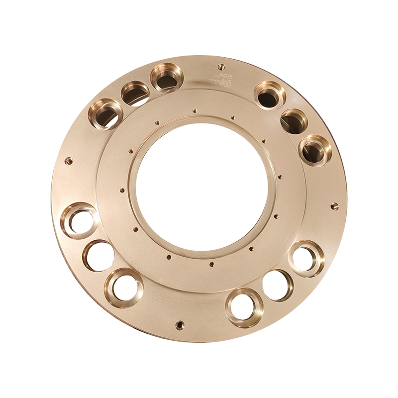
Each blade is bolted to a blade carrier that sits in a spherical or cylindrical bearing pocket in the hub. These bearings must withstand both centrifugal force from rotation and bending loads from thrust, which is why hub bearing surfaces are typically machined from corrosion resistant bronze or stainless steel alloys per classification society material rules such as those published by DNV and ABS.
Step by Step Pitch Change Sequence
The following sequence describes what happens mechanically when an operator moves the pitch control lever on the bridge from ahead to astern.
- Operator moves the pitch control lever, sending a signal to the hydraulic servo pump
- Servo oil pressure increases on one side of the OD box while decreasing on the other
- Oil travels through the hollow tailshaft to the piston chamber inside the hub
- Piston pressure moves the sliding crosshead along the shaft axis
- Crank pins on each blade root rotate the blades simultaneously to the new pitch angle
- Blade angle feedback sensors confirm position and relay it back to the bridge indicator
This entire sequence typically completes within a few seconds to under a minute depending on propeller size and hydraulic pump capacity, which is why controllable pitch systems are favored for vessels requiring frequent maneuvering such as tugs, ferries, and offshore support vessels.
Why Shaft Speed Stays Constant While Thrust Changes
Unlike a fixed pitch propeller, where thrust and vessel direction depend on the engine changing rotational speed and direction, a controllable pitch propeller keeps the shaft turning in one direction at a speed close to the engine's efficient operating range. Thrust is instead controlled purely by blade angle.
Benefit for Engine Load Management
Because the engine does not need to stop and reverse, it can continue running near its optimum load point. Diesel engine efficiency curves published in marine engineering references show that engines operating near rated speed typically achieve 3 to 8 percent better specific fuel consumption than engines subjected to frequent speed changes and idling during maneuvering.
Benefit for Response Time
Because pitch change is a mechanical hydraulic adjustment rather than a full engine speed reversal, response time from ahead to astern thrust is significantly faster, which is critical for vessels like tugs and pilot boats that require rapid thrust reversal during docking operations.
Comparison: Controllable Pitch vs Fixed Pitch Propeller Operation
| Operating Factor | Fixed Pitch Propeller | Controllable Pitch Propeller |
|---|---|---|
| Direction reversal method | Engine reverses rotation | Blade angle reverses, shaft direction unchanged |
| Engine speed during maneuvering | Variable, often reduced | Can remain near constant |
| Response time to reverse thrust | Slower, engine dependent | Faster, hydraulic system dependent |
| Mechanical complexity | Low | Higher due to hub hydraulics |
| Typical application | Cargo ships, bulk carriers | Tugs, ferries, offshore vessels |
This comparison reflects general operating principles documented in marine propulsion engineering textbooks and classification society guidance on propulsion system selection.
Role of the Feedback and Control System
Modern controllable pitch propeller systems do not rely on the hydraulic mechanism alone. A closed loop control system monitors blade position and compares it against the operator's commanded pitch setting.
Position Feedback Sensors
A feedback rod or sensor connected to the sliding crosshead reports actual blade angle back to the control system, which continuously compares commanded pitch against actual pitch and adjusts servo oil flow to correct any deviation.
Combinator Curve Control
Many systems use a combinator curve, a programmed relationship between engine speed and blade pitch, so that as the operator increases the throttle lever, both engine RPM and blade pitch increase together along a predefined efficiency curve rather than independently, reducing the risk of engine overload at low pitch settings.
Maintenance Considerations Specific to the Mechanism
Because the pitch change mechanism relies on hydraulic seals and moving parts inside a submerged hub, maintenance practices differ from fixed pitch propellers.
- Hub oil pressure and seal integrity should be checked regularly to prevent seawater ingress into the hydraulic system
- Blade root O-rings require periodic inspection since they are the primary barrier against water intrusion at the pivot point
- OD box rotary seals are wear items that typically require replacement during scheduled drydocking intervals
- Feedback sensor calibration should be verified after any hub disassembly to keep bridge pitch indication accurate
Following manufacturer service intervals for a system such as the Controllable Pitch Propeller helps ensure the hydraulic pitch mechanism continues to deliver accurate blade angle control over the vessel's operating life.
Summary
A controllable pitch propeller works by using hydraulic oil pressure delivered through the tailshaft to move a sliding crosshead inside the hub, which rotates each blade to a new pitch angle while shaft rotation direction stays constant. This mechanism allows faster thrust reversal, steadier engine loading, and improved maneuvering compared to fixed pitch propellers, which is why it remains the standard choice for tugs, ferries, and offshore support vessels that require frequent and precise thrust control.
Interested in working together or need more info?
Related products
Get in Touch Now!
We're Here to Assist with
All Your Requirements
© Copyright Zhenjiang Jinye Propeller Co.,Ltd. All Rights Reserved. China Marine Copper Propeller Manufacturers Custom Marine Propeller Factory
